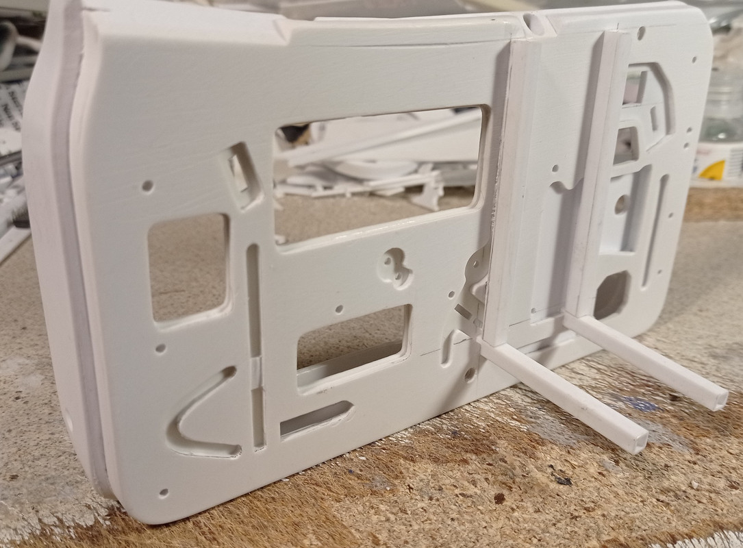
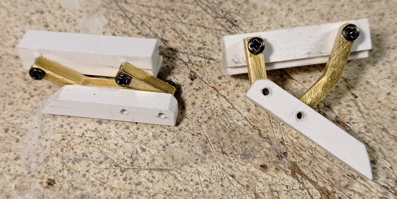
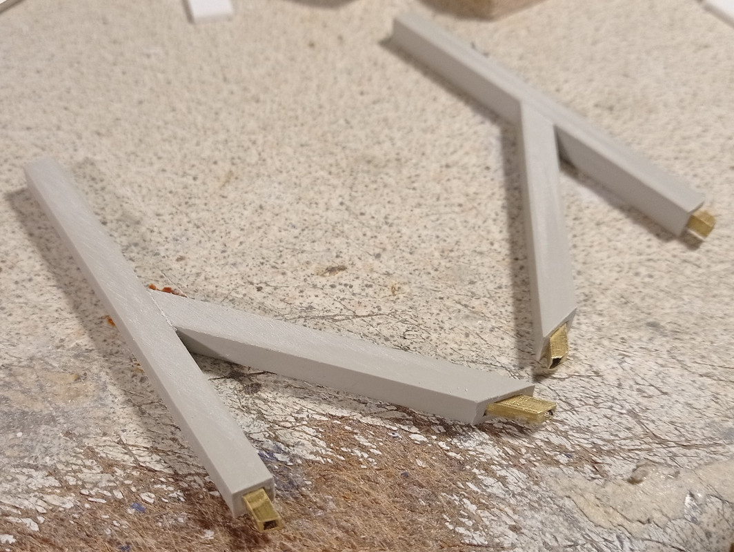
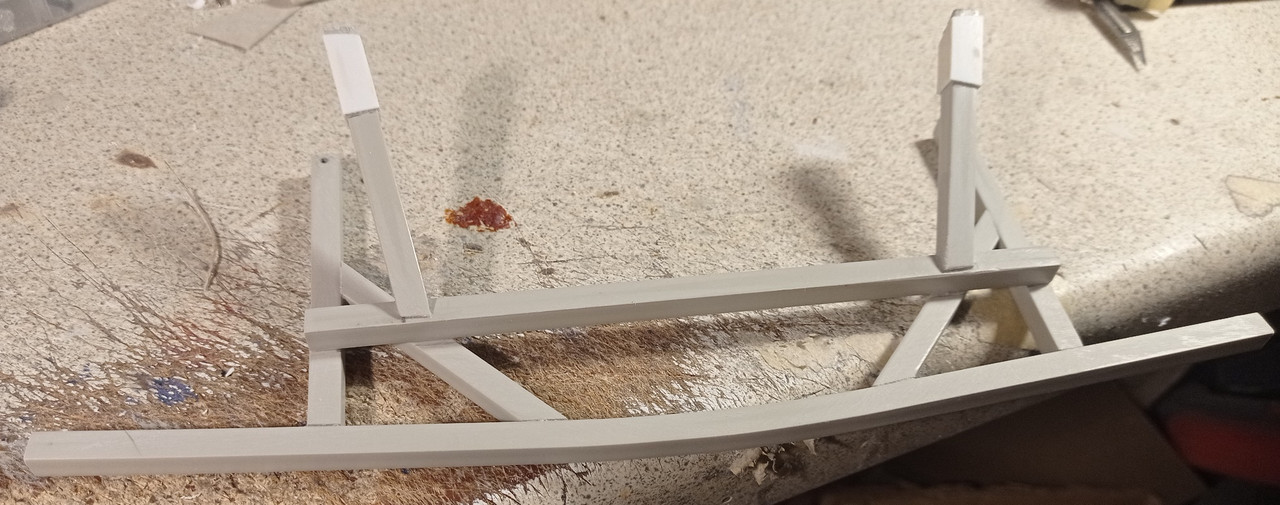
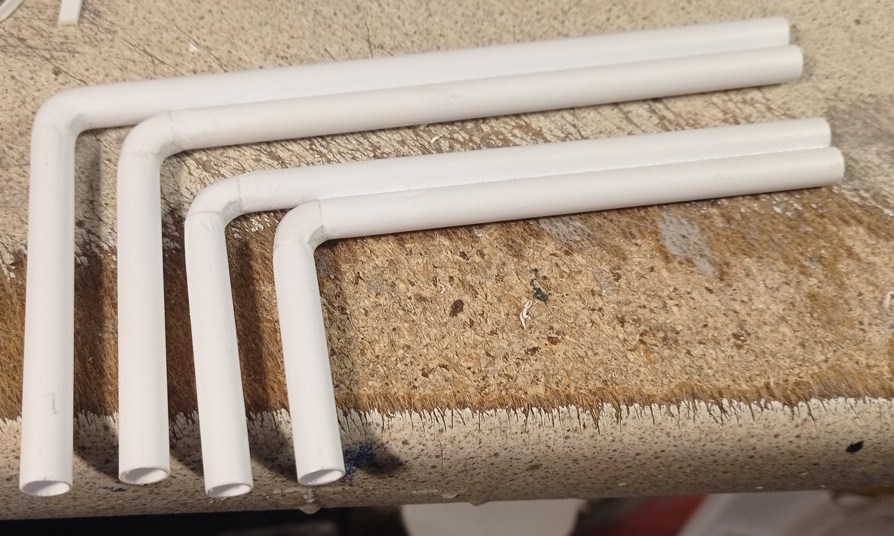
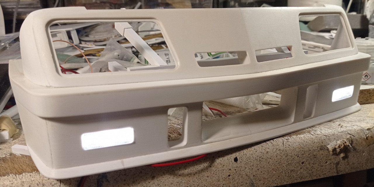
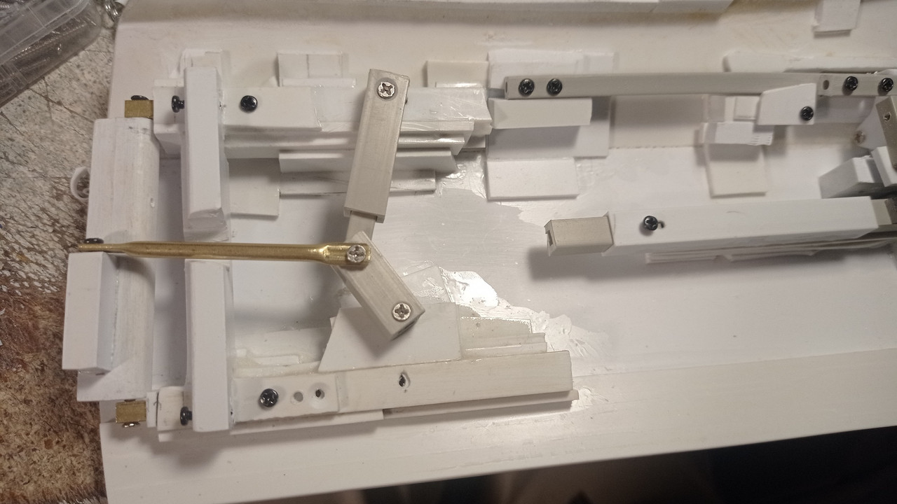
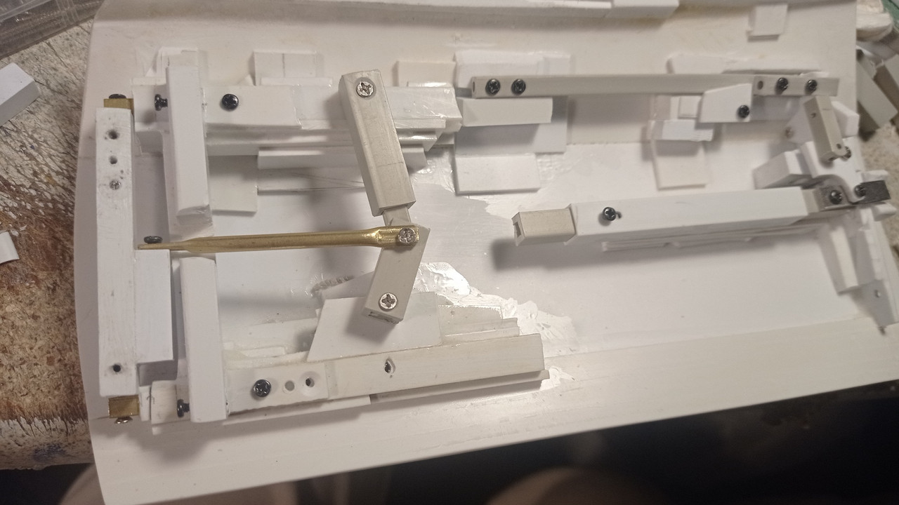
Making the inner bumper. I reinforced the joints with brass rod.
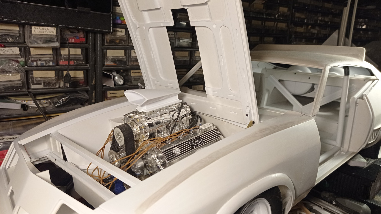
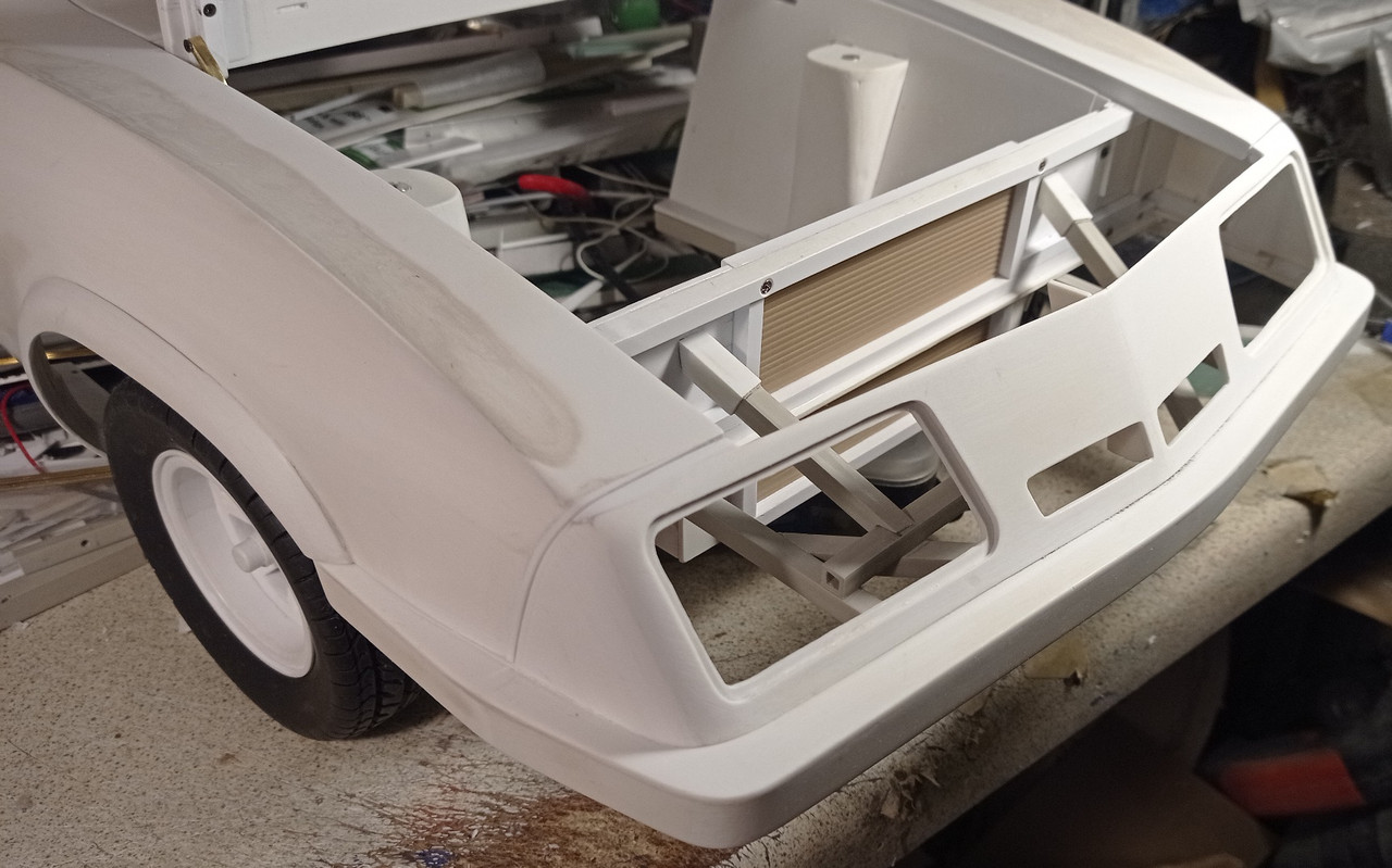
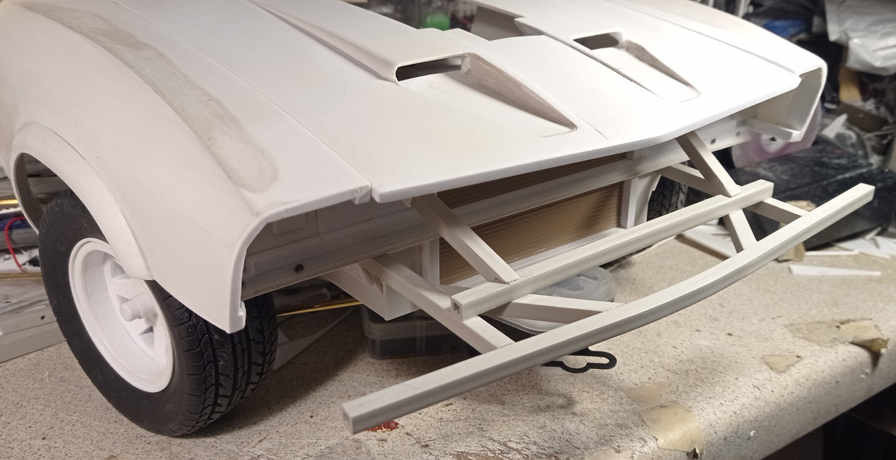
The finished bumper is screwed into place. At first, i wasn't going to bother making this part, as i much prefer how it looks undamaged. Then i realised, much of the inner structure is visible once the hood is opened.
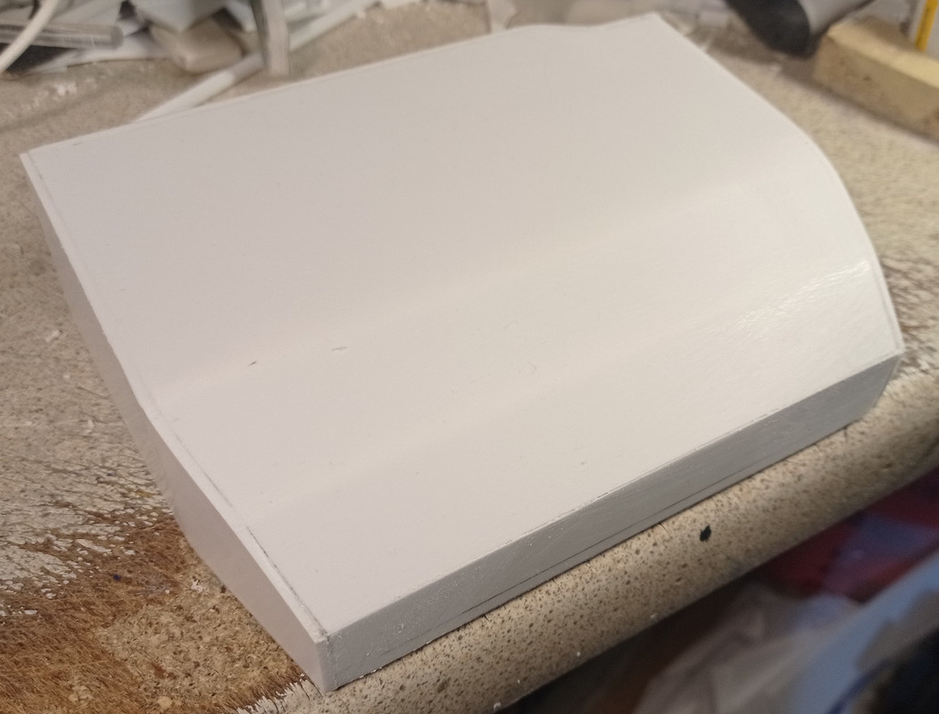
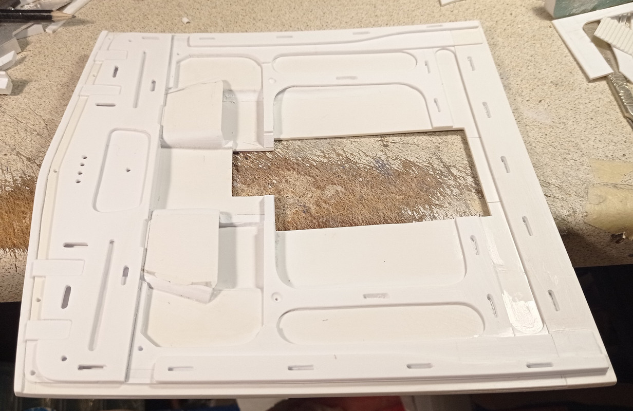
The nose is removable for the sake of completeness.
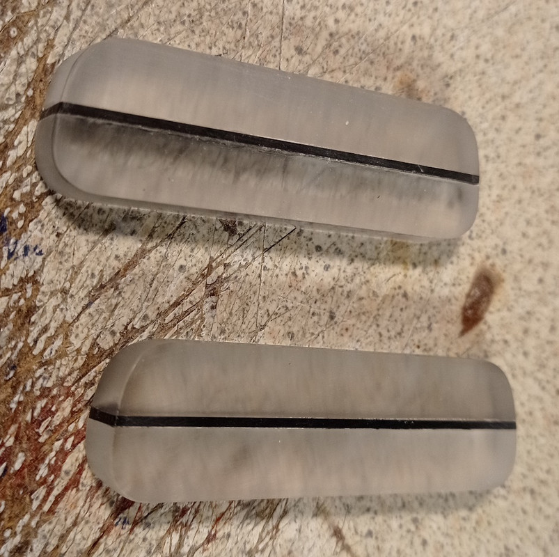
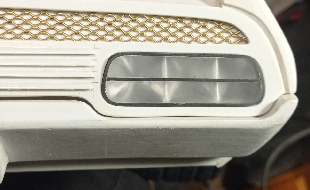
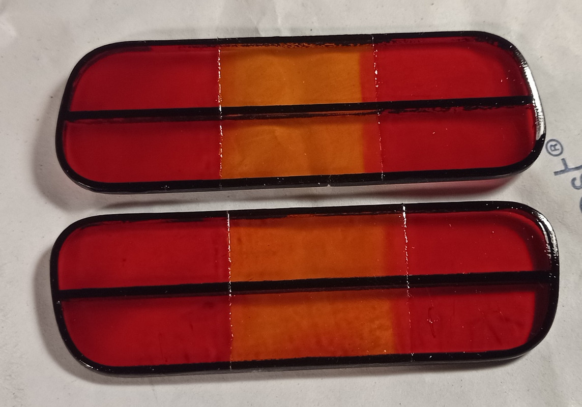
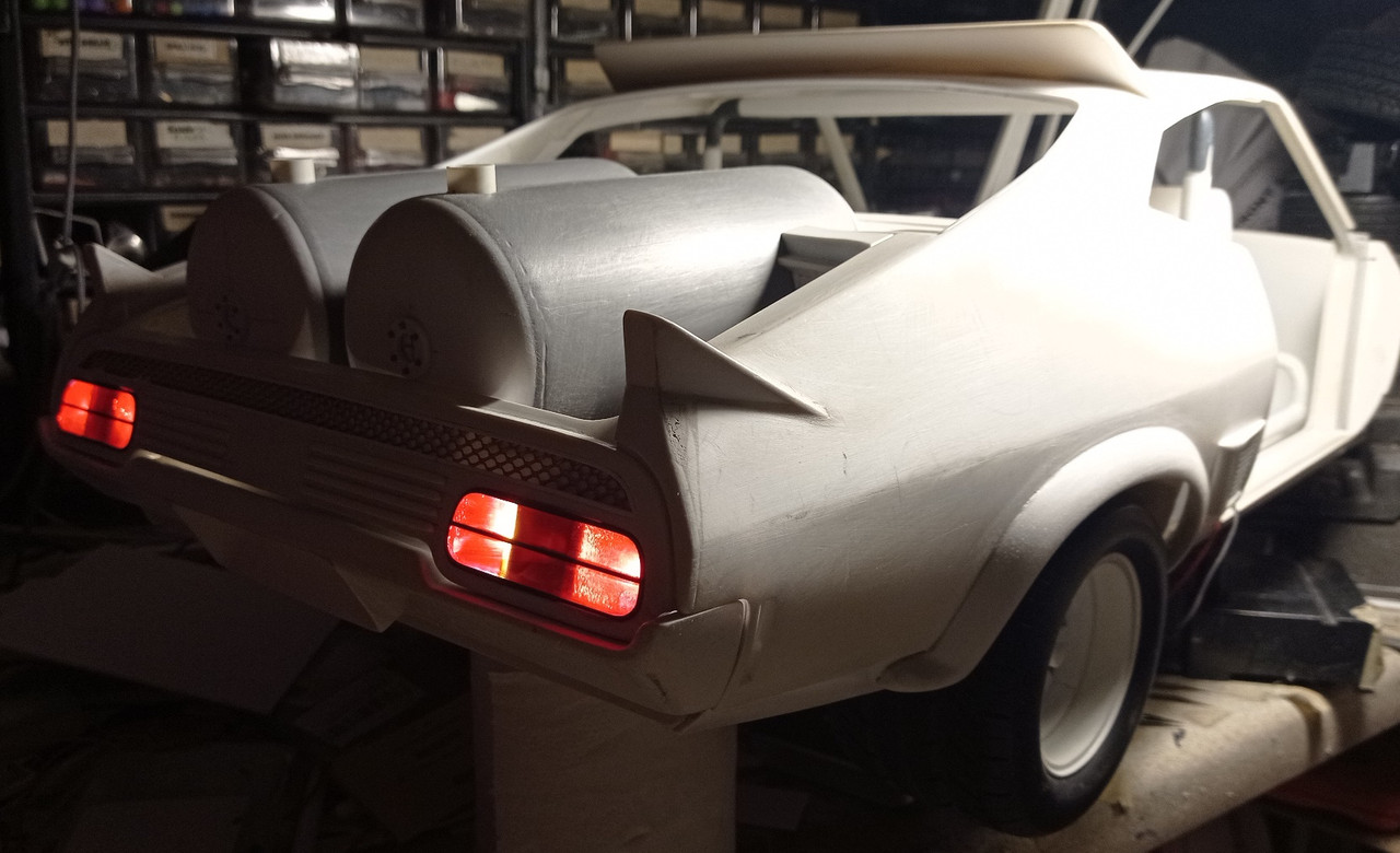
Making the rear lights. These are 2 lengths of 8mm square perspex rod, glued together with a 0.75mm strip of black plasticard between them. The ends are shaped to match the light openings.
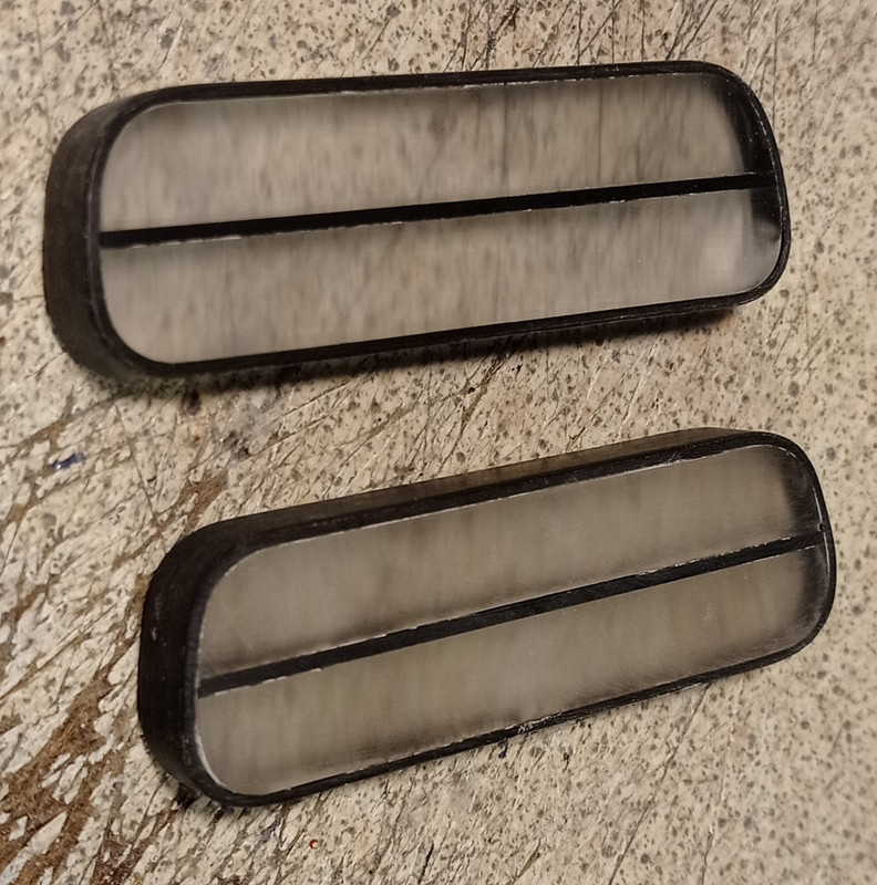
Another strip of plasticard is glued around the edge.
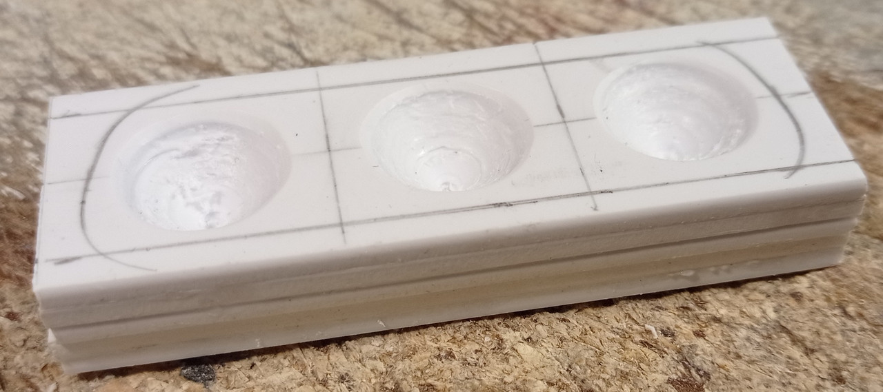
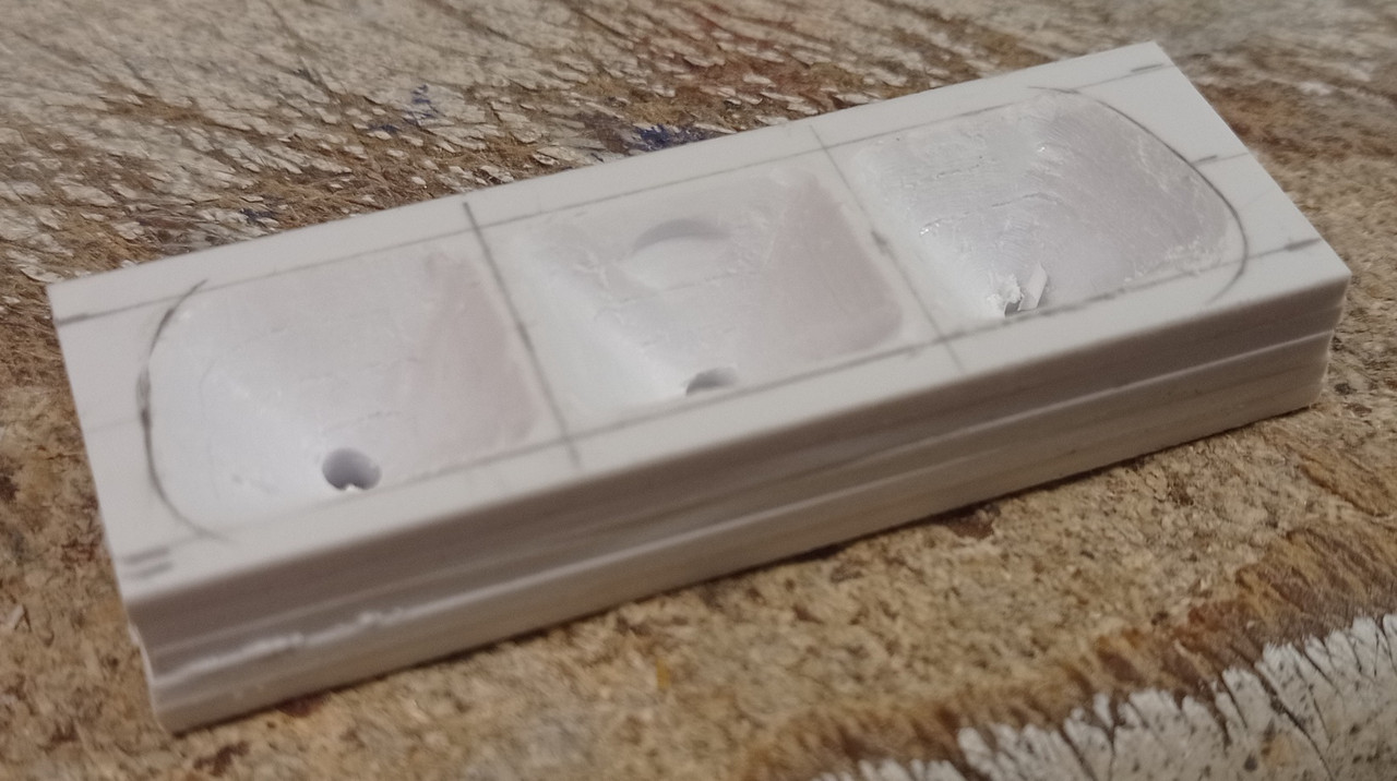
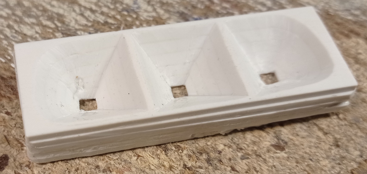
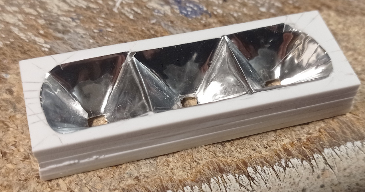
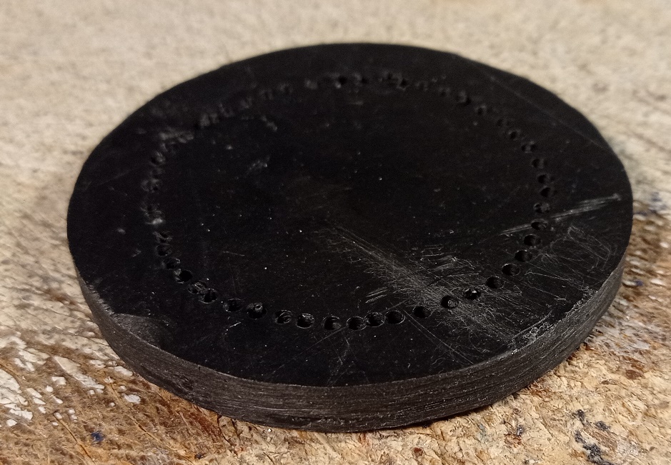
Making the reflectors. This is a stack of 5 2mm thick card glued into a block. The centres are drilled with a countersink bit.
Apologies for the long delay updating this thread. I had been away to Osaka for 2 weeks, but managed to hurt my shoulder whilst i was there. I had to let it rest for a bit, so no work on the car. I hope to get it all done in about 2 months, before the warm weather disappears for rest of the year.
Making the headlights.
The clear part had to be cut from a car sidelight.
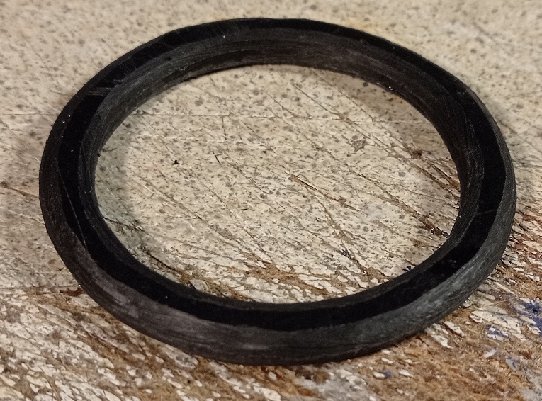
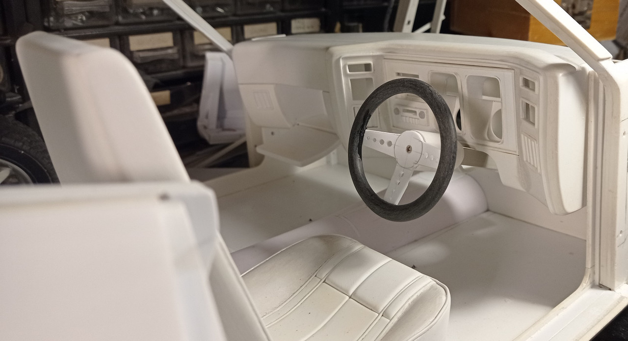
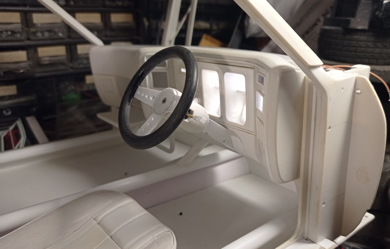
Making the steering wheel. This starts as 3 discs of 2mm plasticard stuck together. I had looked at curtain rings and earrings, but there was nothing the right size available.
The centre is drilled out and the edges bevelled.
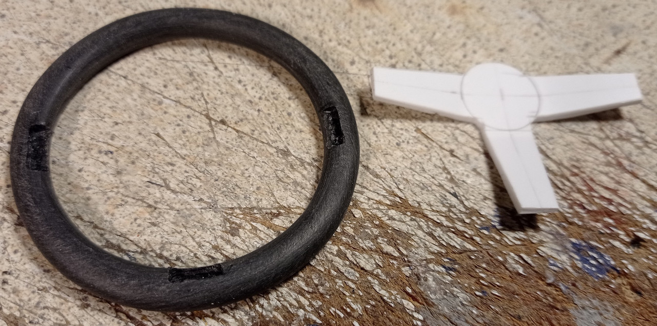
After sanding, 3 notches are cut out for the spokes.
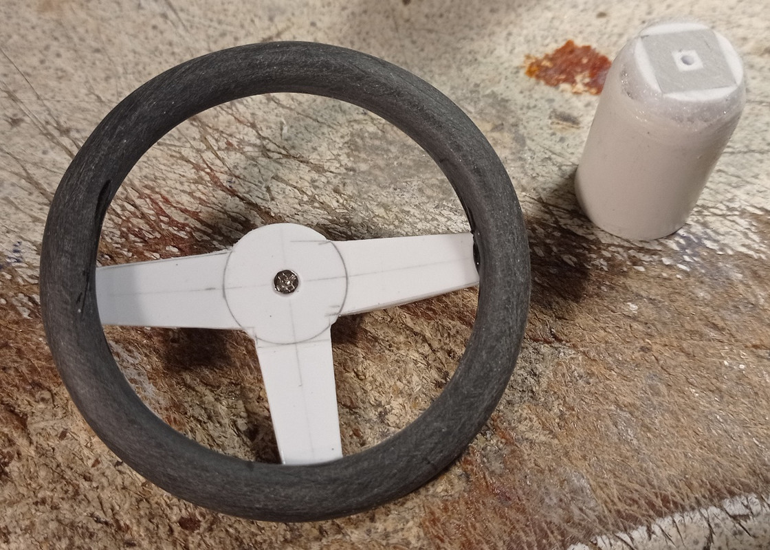
The spokes are glued into place and screwed into the column.
Holes drilled into the spokes and temporarily fitted. The angle needs adjusting, to allow more room for the driver's legs.
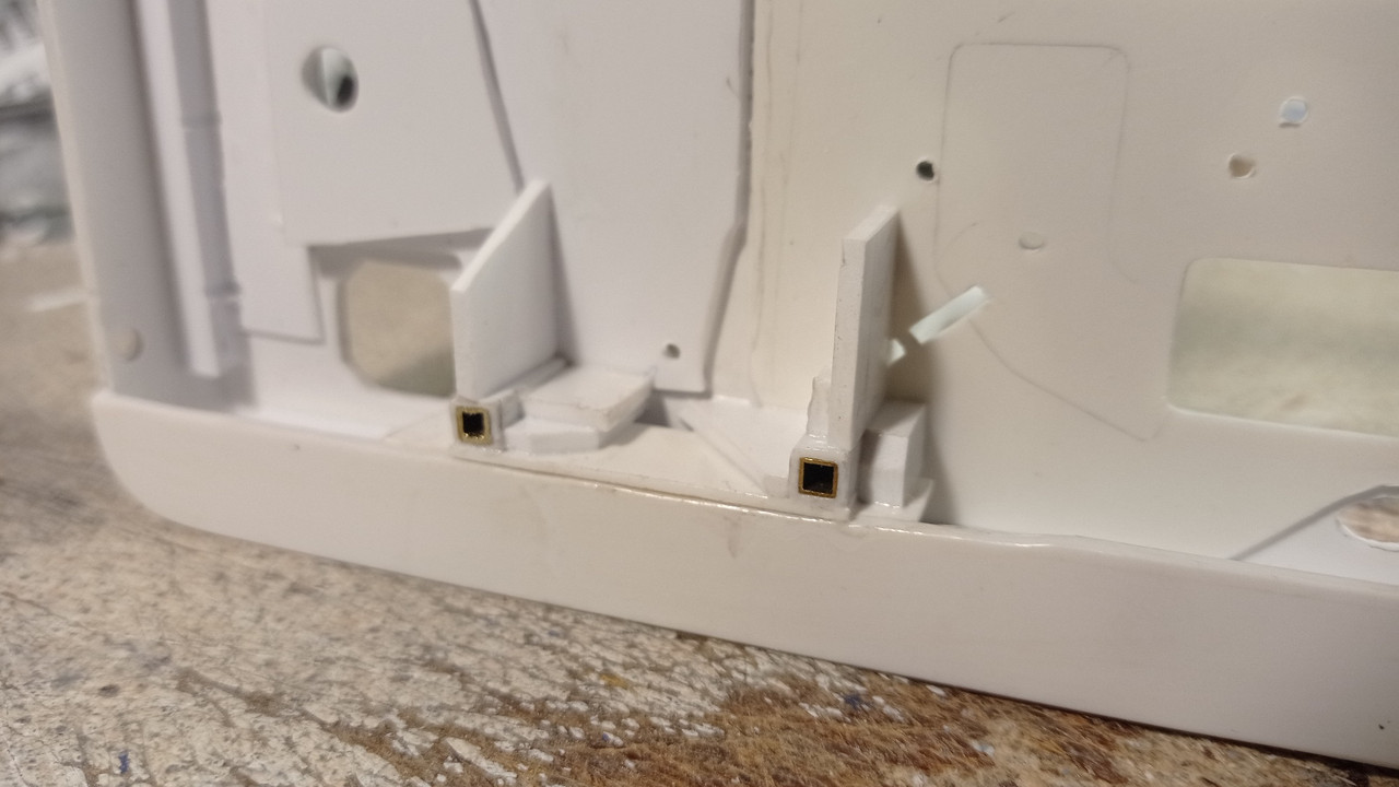
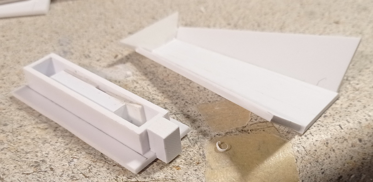
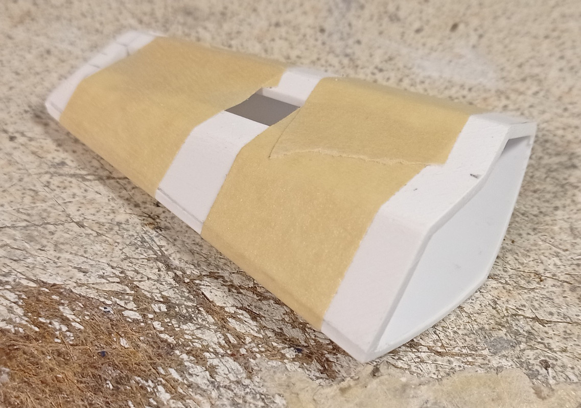
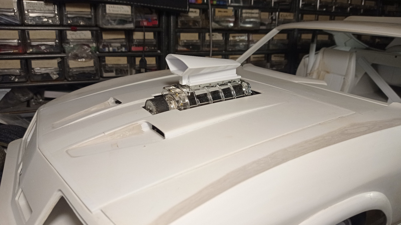
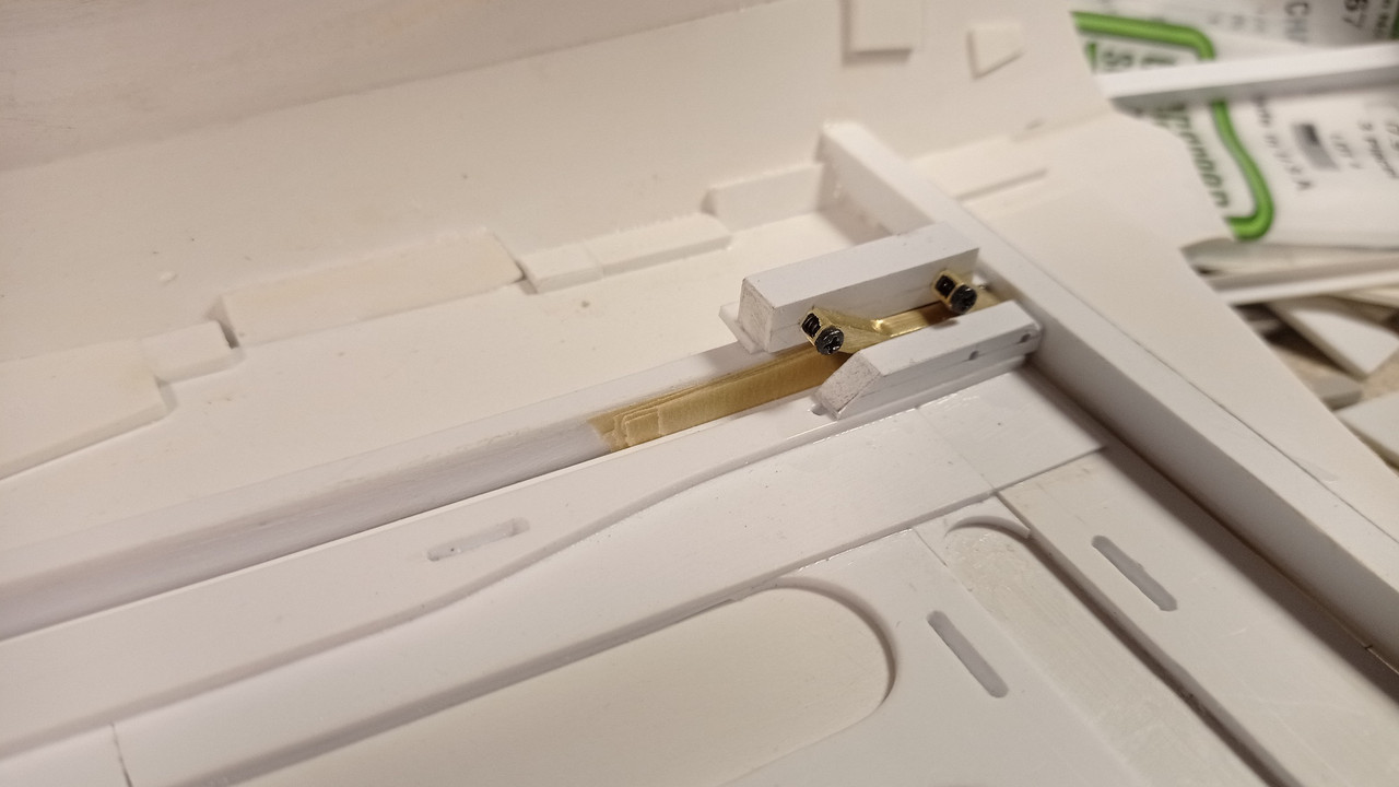
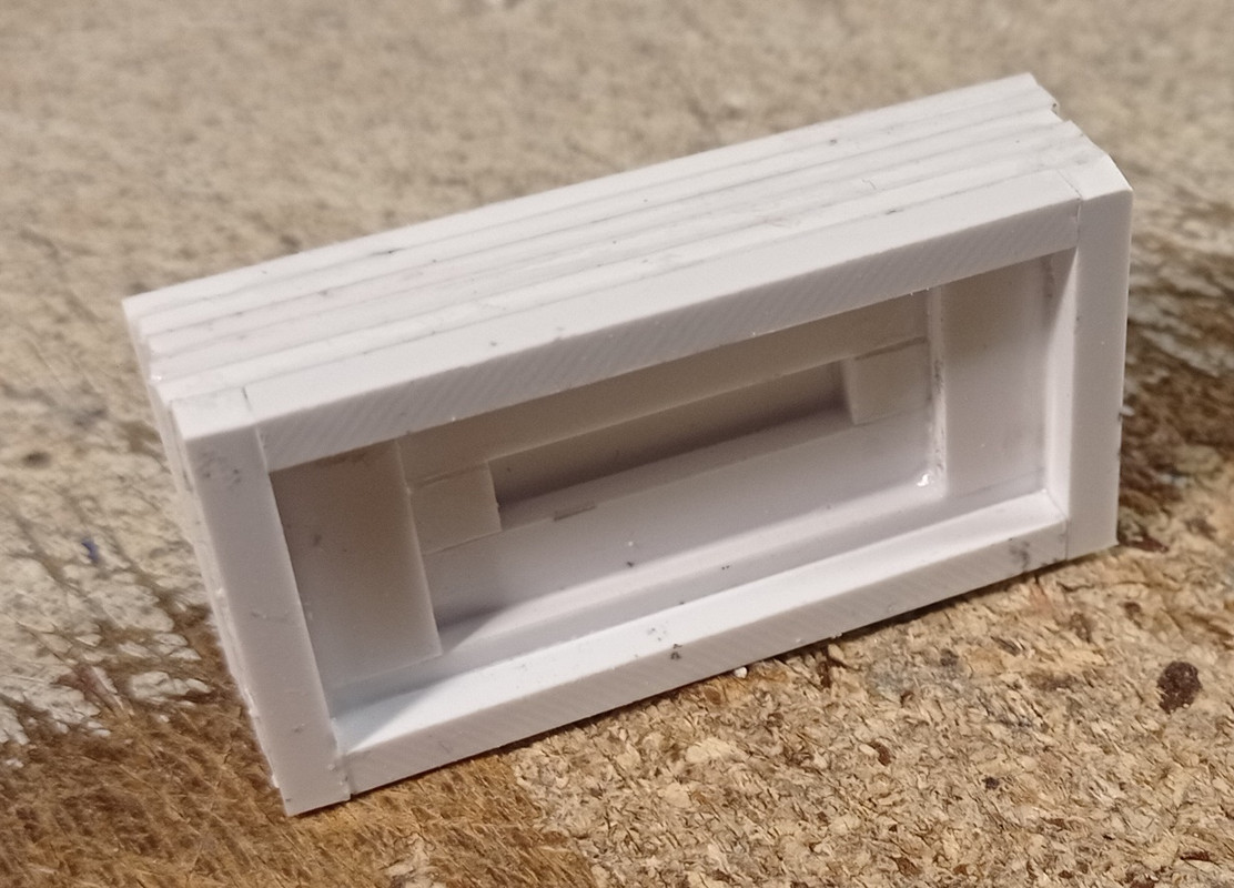
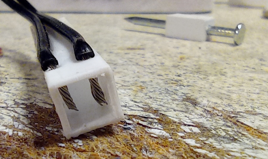
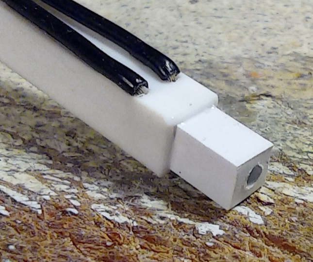
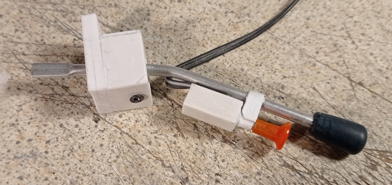
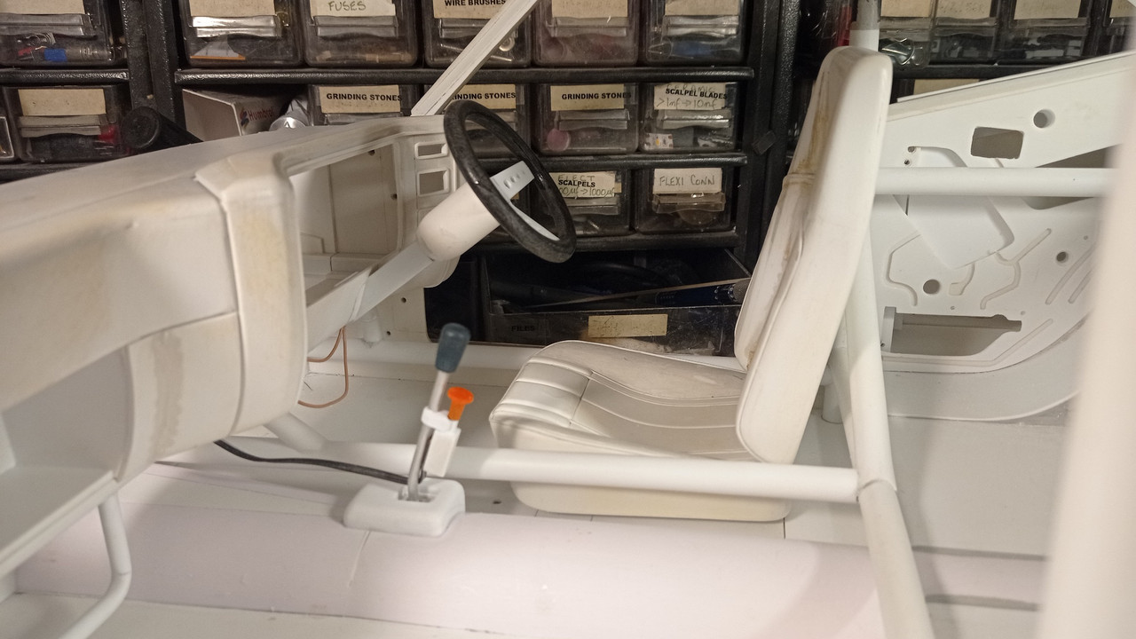
Making a small but important feature, a functional blower switch. 2 wires are glued inside a square tube and a piece of square rod is drilled to take a nail.
The rod is glued to the tube.
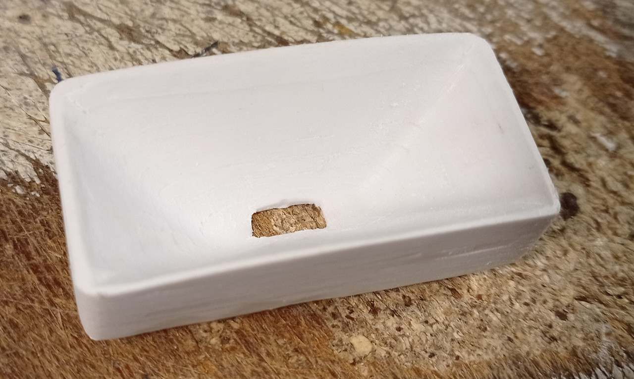
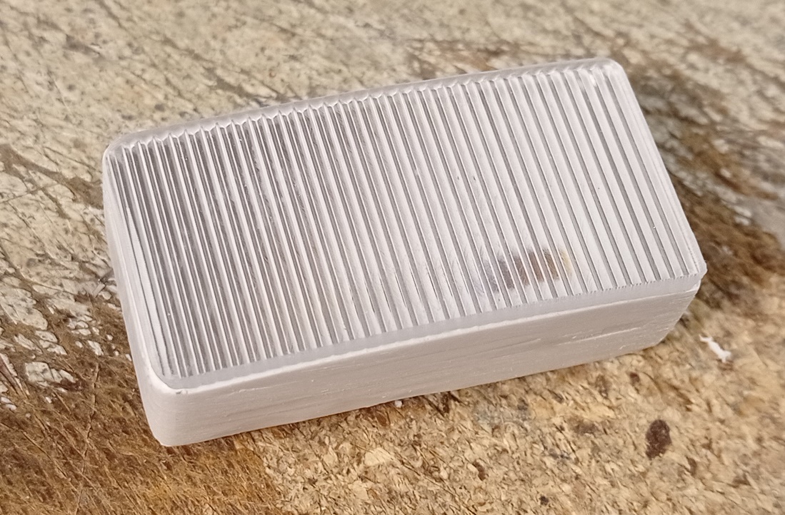
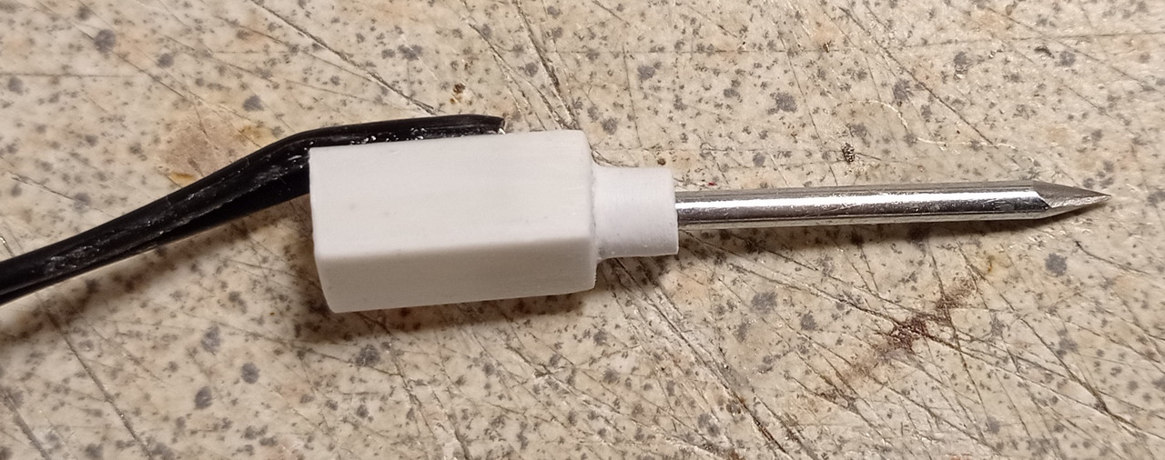
The collar is rounded off and the nail is inserted from the opposite end.
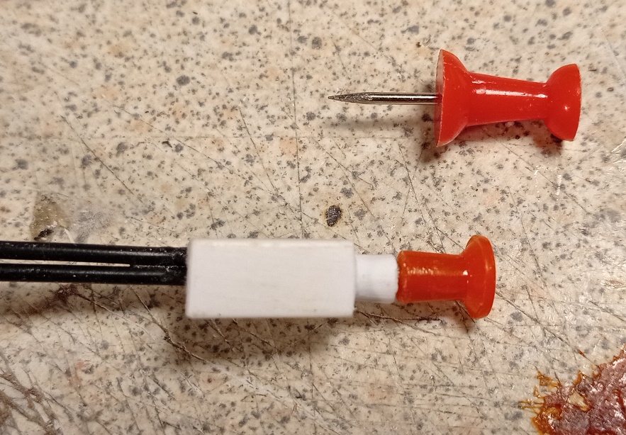
The nail is cut down and a modified push pin glued to the end. When pulled out, the head of the nail touches the 2 wires to complete the circuit.
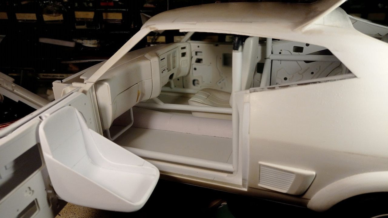
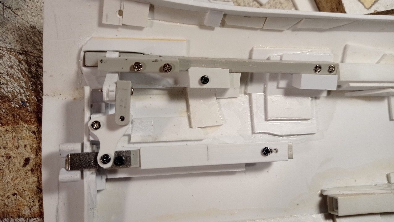
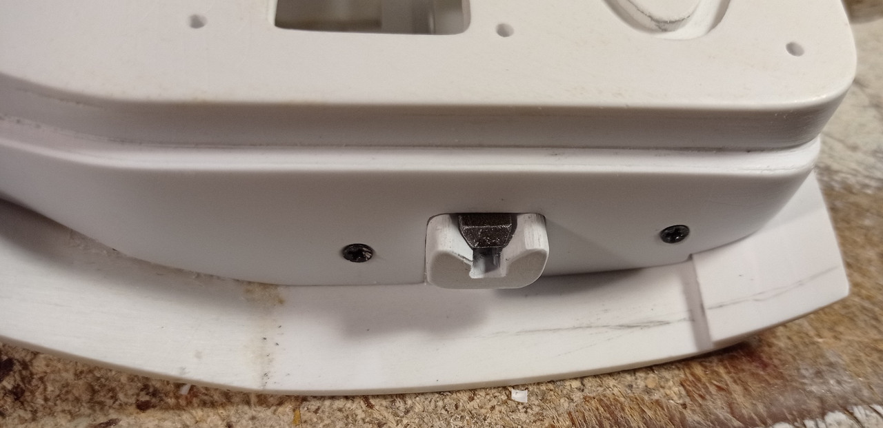
Tackling one of the fiddliest jobs on the car, making functional door handles. The placement of each part is critical, so that the door panels will align exactly when closed.